
Process data flow
Input parameters and results
By looking at a process as a black box, we define what data is necessary to run it and what results are produced by the process. In other words, we treat the process as a function, specifying its input and output parameters.
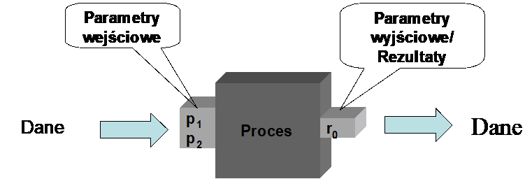
Figure 1. The process seen as a black box
This approach is particularly desirable when a given process is invoked by another process (as a subprocess) or when the process is launched using software interfaces.
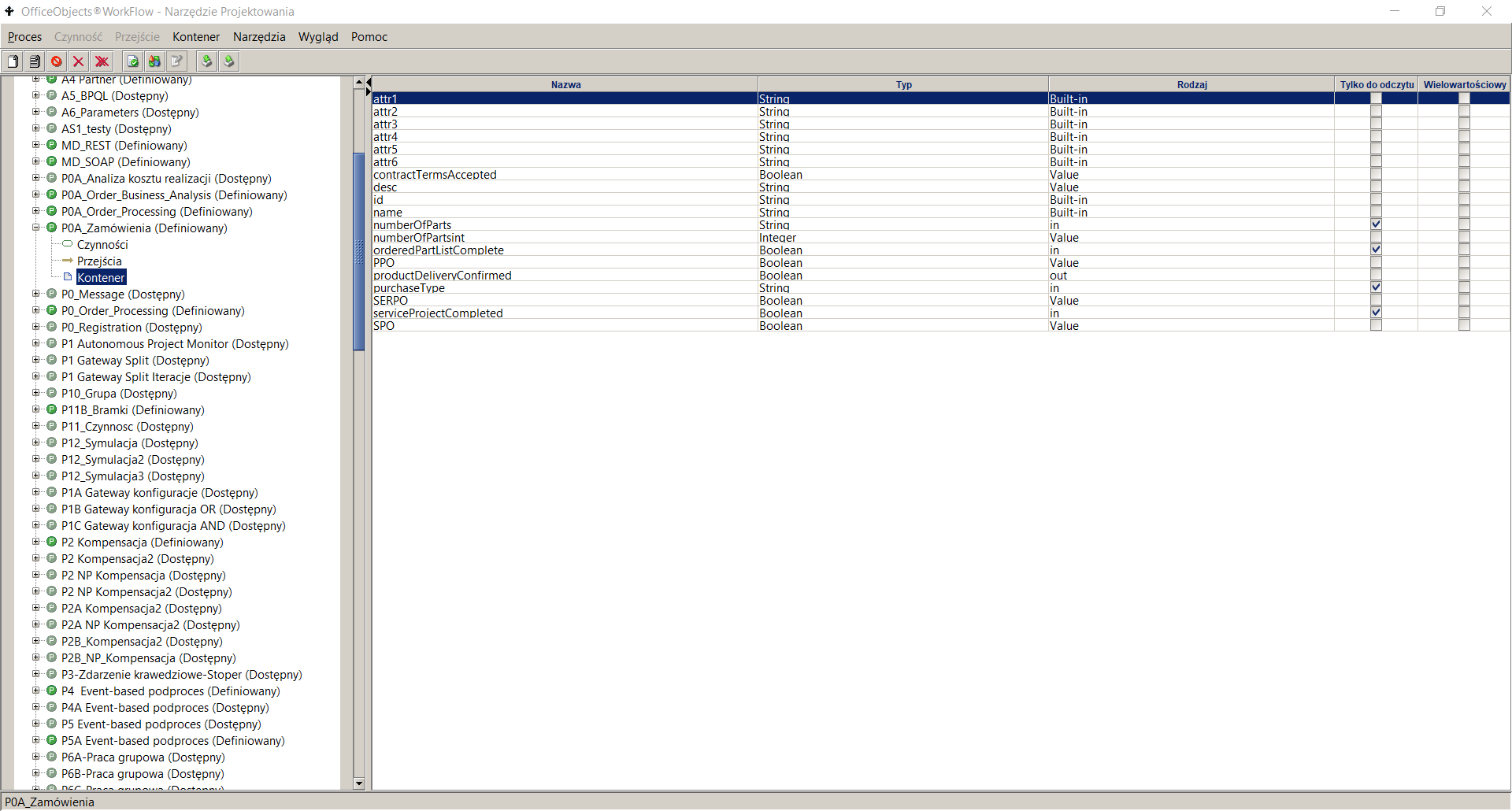
Figure 2. Process container attributes
To define a new process input or output parameter in the process design tool:
- go to a given process in the process definition list panel
- go to the Container node , the right pane will display a list of currently defined process container attributes
- Select the menu item Container->Add
- Enter parameter data, including:
- Name – provide a unique name. Basically, the name is a sequence of alphanumeric characters starting with a lowercase letter. Each new word is appended to the existing ones and starts with a capital letter. Examples of names: employeeName, businessTripBudget.
- Type – for the input parameter, select the value in . For the output parameter – the value out . If the given input parameter is also used as an output parameter (result), set the Type to in/out .
- Read Only – indicates that the parameter will be used only to read data and an error will occur when trying to write it. In the case of an input parameter, this parameter is automatically set to Read Only . In the case of an output parameter, this parameter should be left unchecked.
- Type - type of the attribute, select the appropriate type from the list of available types.
- Multi-value – if the parameter takes multiple values, this box should be checked.
- Mandatory – if the attribute value is always required, then this field should be checked. From a practical point of view, this option only makes sense for input parameters because most often the output parameter value is not known at the start of the process.
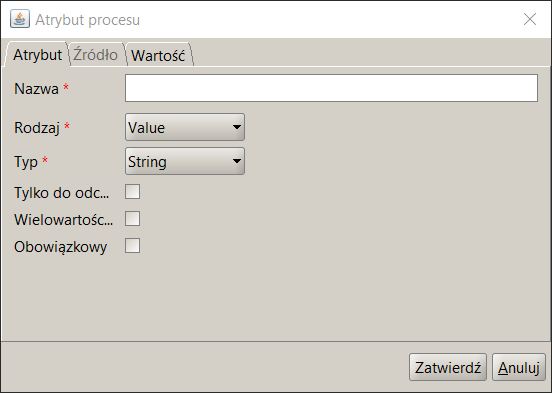
Figure 3. Adding a process attribute
A data container attribute is a global variable of a process used to store temporary values during process execution, to perform complex data mappings in a process, or to store pointers used in the executing process.
Each attribute has a specific name, type, kind and cardinality. In addition to the standard attributes, the container attribute contains two additional ones , namely refreshable fields and retrieveExpr . The description of these fields is presented in Table 1 .
| Attribute name | Attribute description |
|---|---|
| Refreshable | Specifies whether the attribute value must be recomputed when it is read. If the attribute is set to true , the data container attribute value is recomputed according to retrieveExpr. Otherwise, the attribute value is retrieved directly. |
| retrieveExpr | An expression specifying how to retrieve the value of an attribute. |
Table 1. Process Data Container Attribute Specification
The BPQL expressions can use process variables stored in the data container. Process-level variables are used to store data that controls or is processed by a process. To use a variable in a BPQL expression, precede its name with a "$" character.
$<variable_name>
In case the global variable is multi-valued , the reference to its n-th element can be realized using the GetMultiValueAttribute function
In some processes, there is no need to define input and output parameters. This is especially true for processes where input parameters are de facto entered in the first activity, most often using a form. In such a case, this data is defined as global variables and not as input or output parameters .
In order to improve ergonomics it is possible to dynamically add input, output parameters and global variables in any field accepting a BPQL expression ( pre , post-action , participant , instance owner , parameter value application , etc.). To do this, enter the correct name of the parameter or variable , select it and choose the 'Add' option available by clicking the right mouse button.
Data inside the process
The input parameters of the process are passed to individual activities. Since these activities call applications , the input parameters of the process are mapped to the input parameters of the application. For example, as shown in Figure 4 , in activity A, the input parameter of the process p1 maps to the input parameter a 1 of application A 1 . As a result of executing activity A, the result of executing application A1 is returned . This result should be used as the input parameter a3 of application A2 executed in activity B. To do this, we need an object inside the process that stores the value of the result returned by application A1 . Global variables (described in the following section) are used for this purpose . In our example, we have a global variable v1 . This variable is used to perform mapping to the input parameter a3 .. After executing activity B its result is stored in the variable v2 . This variable is in turn used as an input parameter to application A3 called in the activity C. Ultimately, the result of the activity C is mapped to the process result r1.
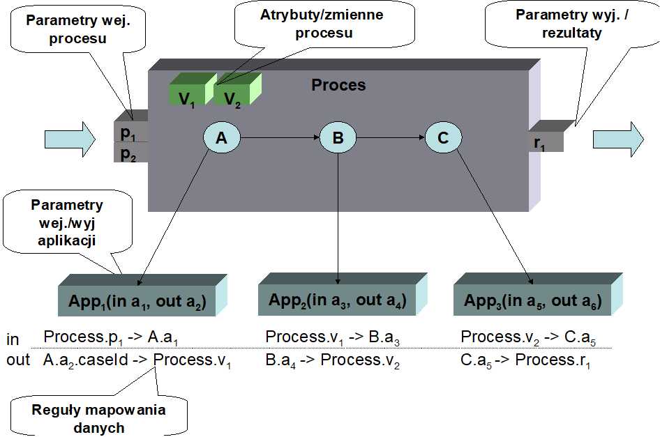
Figure 4. Data flow inside the process
To sum up, the example shows that:
- the input data for defining the data flow are the process input parameters
- the process results are placed in the process output parameters
- applications executed in activities need input data. This data is provided based on the input parameters of the process or the results of applications executed in previous activities.
- applications produce results . These results are used as input parameters applications performed in other activities, or returned as results of process execution.
- Global variables are used to ensure proper data flow between the activities performed within the process.
Data flow rules are defined at the level of parameters of the applications being called. In the case of an input parameter, you can define what value will be substituted for this attribute. The expression can be any BPQL rule. In the case of output parameters , you can define to which variable the result value will be passed.
Global variables
Global variables can also be used to "match" the results of one application to the input parameters of another application. For example, if application A generates two results: the name and surname of a quality controller, and application B requires the name of the controller (name + surname), then a global variable can store the text that is a concatenation of both returned results and pass it to the second application in this form.
As indicated earlier, a process global variable can be seen as a temporary "container" that stores intermediate values that are needed in the process to ensure proper data flow. A global variable is defined within the process container . Accessing a global variable in any BPQL rule is very simple, via $<variable_name> . This is the same way as for input and output parameters . For example, to write to a global variable *$*delegatename first name plus dot plus delegate's last name just execute the following instruction:
$ delegatedname := $ delegatedname + ' '+$ delegatedname ;
The following parameters are defined for a global variable :
- Name – unique name of the variable at the process level. Basically, a string of alphanumeric characters starting with a lowercase letter is given as the name. Each new word is appended to the existing ones and starts with a capital letter. is not recommended to use Polish diacritics in the attribute name.
- Type – there are several possibilities here: built-in variables , variables saved in the data structure of the docuRob® WorkFlow system ( value ) and variables saved in external systems but only referenced in the docuRob® WorkFlow system ( reference ). The individual types are discussed in the individual subsections.
- Read-only – if a given parameter will be used for read-only purposes, this option should be set. This applies to value type variables with a known initial value, which are used in the process as constants. Setting the default (initial) value is performed in the Add process attribute window, on the Value tab
Figure 5. Defining the default value of a process variable
The default value can also be assumed by variables of the Document type (XML document). This allows you to create an XML document template to which individual nodes will then be added. Another use of this option can be to save long names of concepts from an ontology in variables .
- Type - attribute type, select the appropriate type from the list of available types. Type selection can be done for variables of type value and reference . The following simple types are allowed:
- String – any text string. The text string can contain any characters enclosed in apostrophes. Examples: 'alabama', 'ala bama', 'Spare parts', 'Part no. #234',
- Integer – whole value. Examples: -123, 345, 0,
- Double – real value. The sign separating the integer part from the fractional part is the character "." Examples: 123.56, -23.67,
- Timestamp – date and time. When entering constants, only dates can be entered. Allowed date formats are: YYYY-MM-DD and YY-MM-DD (where: Y- year digit, M- month digit, D- day digit). Examples: 2001-01-01', '2008-07-23',
- Boolean - logical value. Allowed values are: true and false , case sensitive),
In addition to the simple types, there are also three complex types:
- Binary – represents a file not interpreted by the docuRob® WorkFlow system . It can be a file of any format that is, as part of the process, passed between activities.
- Document – a complete XML document (file) that can be interpreted by the rules available in BPQL.
- Node – a fragment of an XML document (also a file) representing an XML node that can be interpreted by the rules available in BPQL.
- Multi-value – if the parameter takes multiple values, this box should be checked, Adding additional values can be done using program interfaces. The use of these variables is described in the next subsection,
- Mandatory – if an attribute value is always required, then this box should be checked. From a practical point of view, this option only makes sense for variables with an initial value.
Built-in variables
Built-in variables are a limited set of special variables built into the docuRob® WorkFlow data model . Because they are located in this way, access to them is fast. These variables are primarily used to store information that:
- identifies external data related to the process (e.g. document identifier, case identifier),
- stores data displayed in the task list regarding the supported objects, e.g. correspondence number, document name, etc. This data can be sorted together with basic task data such as task name, performer, completion date, etc.
It is assumed that built-in attributes receive a value at the beginning of the process and then their value does not change. In particular, this is crucial when these attributes store identifiers to external objects or numbers appearing in the task list. Additionally, these are text attributes . If we store numeric values in them, the sorting may be different than required (it is necessary to fill the significant digits in front of the number with spaces). These variables can be used to create names and descriptions of activities.
There are currently nine built-in text attributes in the system:
- name – it is recommended to use this variable to store the name, signature or number of the object (root of objects) processed in the process
- id - it is recommended to use this variable to store the identifier of the object (root of objects) processed in the process
- desc - it is recommended to use this variable to store the description of the object (root of objects) processed in the process.
- attr1, attr2, attr3, attr4, attr5, attr6 – six attributes with any interpretation.
Variables of type value
variables are saved in extensible process structures. Access to them is not as fast but they do not require repetitive reading from an external system as is done in the case of pointer variables . On the other hand, these variables can be multi-valued and take any simple or complex type .
Pointer variables
variables are the most flexible because they allow reading data saved in an external system. There are two possibilities based on the data source:
- database – the system is provides functions to read data from the database. It is assumed that this data is available for reading by the system user (appropriate views are needed). Reading is done via the JDBC protocol. In order to read the information, the design tool needs the following data:
- column name - the name of the column from which the variable value will be read,
- table name – the name of the table where this column is located,
- condition – search condition for a record in the referenced table. Most often, the condition uses a selection criterion related to the identifier of the object processed in the process, stored in the built-in variable $id.
Multi-valued variables
Multi-valued variables allow handling situations where, due to the multiplicity of paths in the process, different values of the same data occur. An example is an opinion made by several employees (one activity, but many instances of this activity) - many individual opinions.
Individual values in a multi-value variable are identified by a key . The key can be a consecutive integer, but it can also be the identifier of the activity instance in which the value is stored. Both in the activity A and in activity C we write the value of the variable "cost . The value of the variable is written by the API of programming interfaces .
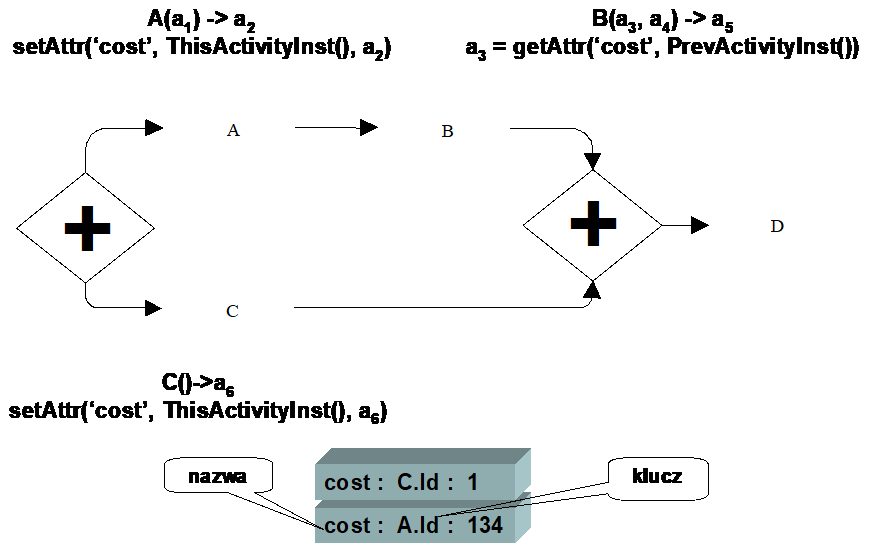
Figure 6. Using a multi-value attribute
Since the paths where activity A and activity C are located are executed in parallel, it is required to store the cost data as two values. Suppose that in activity B we want to refer to the value stored in activity A . To achieve this, we need the appropriate keys . Using a simple index does not work, because it is still not known which value was stored in activity A .
The solution may be using the activity instance identifier as the key . In this approach, reading the value stored in activity A is simple: in activity B we refer to it using the BPQL function for reading the identifier of the previous activity instance and pass this identifier as the key for reading the cost value.
Local variables
In addition to global variables defined for a given process and available everywhere in it, there are local variables available within individual activities. Since these variables are built-in variables, access to them is fast. Their purpose is analogous to global built-in variables .
currently four built-in text attributes in docuRob ® WorkFlow :
- attr1, attr2, attr3, attr4 – attributes of any interpretation.
They can be accessed in any BPQL rule (in the context of an activity) using the GetActAttrValue and SetActAttrValue functions .
Data flow rules
Data flow rules are defined at the level of parameters of the applications being called. In the case of an input parameter, you can specify what value will be substituted for this attribute. The expression can be any rule in BPQL. An example of such an expression is presented in Figure 7
Figure 7. Defining the value of the application input parameter
In the case of output parameters , you can define to which variable the result value will be passed (see Figure 8 ). Other BPQL expressions are not allowed here. The system will not report an error even if another BPQL expression is entered for the output attribute. This error will appear only at the execution stage
Figure 8. Defining the value of the application output parameter
Control flow
Based on the flow defined in the process model, we define:
- Control flow conditions – these conditions are represented as BPQL rules,
- characteristics of activity flows , indicating how control is connected and separated.
- actions performed before the activity begins and after its completion.
Transition Conditions
Transition conditions are logical expressions that determine whether a transition will be executed or not. A condition is represented by a BPQL rule and it can contain arbitrary language elements that ultimately evaluate to a Boolean type . In practice, a control flow condition is defined based on global process variables and BPQL functions that provide data on objects and forms processed by the process.
To define a condition, you must be on the Process Model tab , select the appropriate transition and double-click with the left mouse button. A dialog box for entering transition data appears on the screen. It provides the following information:
- From activity – number and name of the starting activity from which the transition is defined. Read-only value.
- To activity - number and name of the final activity to which the transition is defined. Read-only value.
- Name – name of the transition. This name appears in the Process Model tab .
- Description – additional information about the transition, completed for documentation purposes.
- Condition – BPQL language expression.
For transitions, you can optionally omit the transition name , in which case the condition will be shown on the Process Model graph instead of the transition name.
When defining the transition condition, it is possible to insert logical operators : AND, OR, NOT using the buttons located in the lower left part of the window. To select a global variable or a built-in BPQL function , click the Insert button. A standard window for entering information about the organizational structure , built-in functions and global variables appears on the screen . On the Org. Structure tab , you can select four data categories:
- Function – a list of BPQL functions that can be used to define a condition appears on the screen. The function is selected by double-clicking on its name or by highlighting the function and clicking the “ Select ” button.
- Position – provides a list of positions defined in the system. This list may vary depending on the dictionaries of a given client.
- Group – allows you to select a functional group or organizational unit defined in the docuRob ® WorkFlow system or synchronized with the appropriate employee management system.
- Employee - a list of employees working in a given group or organizational unit selected from the drop-down list of groups and units.
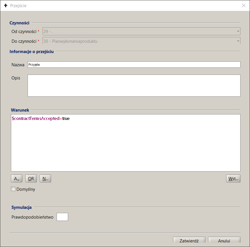
Figure 9. Defining control flow rules
The selection of BPQL Functions and other elements available within the process ontology is presented in Figure 10 .
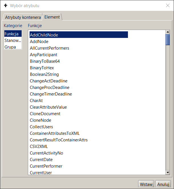
Figure 10. Selecting an element of the BPQL expression
The selection of a global variable (container attribute) is performed on the second tab (see Figure 11) . After selecting it, a list of available attributes is displayed along with information about the type and kind of the variable . Double-clicking on the variable selects it.
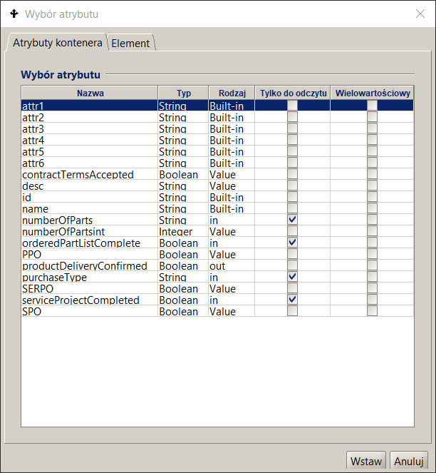
Figure 11. Selecting the global variable of the BPQL expression
Connection and separation of control
Joining and separating control is usually performed by control activities . The characteristics of such an activity are specified already during the process modeling, in particular the type of activity (i.e. joining or separating control, parallel execution , optional or alternative ). During the definition, only the name and description of such an activity remain to be provided.
For each activity there is a defined method:
- The control joins performed on entry to this activity. By default, this is an alternate join (join type XOR) meaning that each tag that reaches the activity will start it. Other possibilities are AND and OR joins . In the first case, the activity will start only when all of its inputs are active . In the second case, the activity will start when all of the activities related to this join (i.e. those contained in the paths that were started when the control separation that is now being joined) have finished.
- Separation of control performed on exit from activity. By default this is an optional token flow (OR) meaning that control will be transferred to all transitions for which the transition condition is met . Other possibilities are either AND or XOR token flow control types. In the first case, transfer of control after the activity is completed will only occur if all transitions leaving the activity are elligible to run. In the second case, transfer of control will be possible as long as only one outgoing path is possible to run (for the rest of the transitions conditions will not be met).
To modify the adopted method of control connection/separation , you should:
- enter the properties of the activity.
- In the left pane of the activity properties dialog box, select Flow .
- In the right panel, set the appropriate options related to merging and separating control.
- Click the Confirm button .
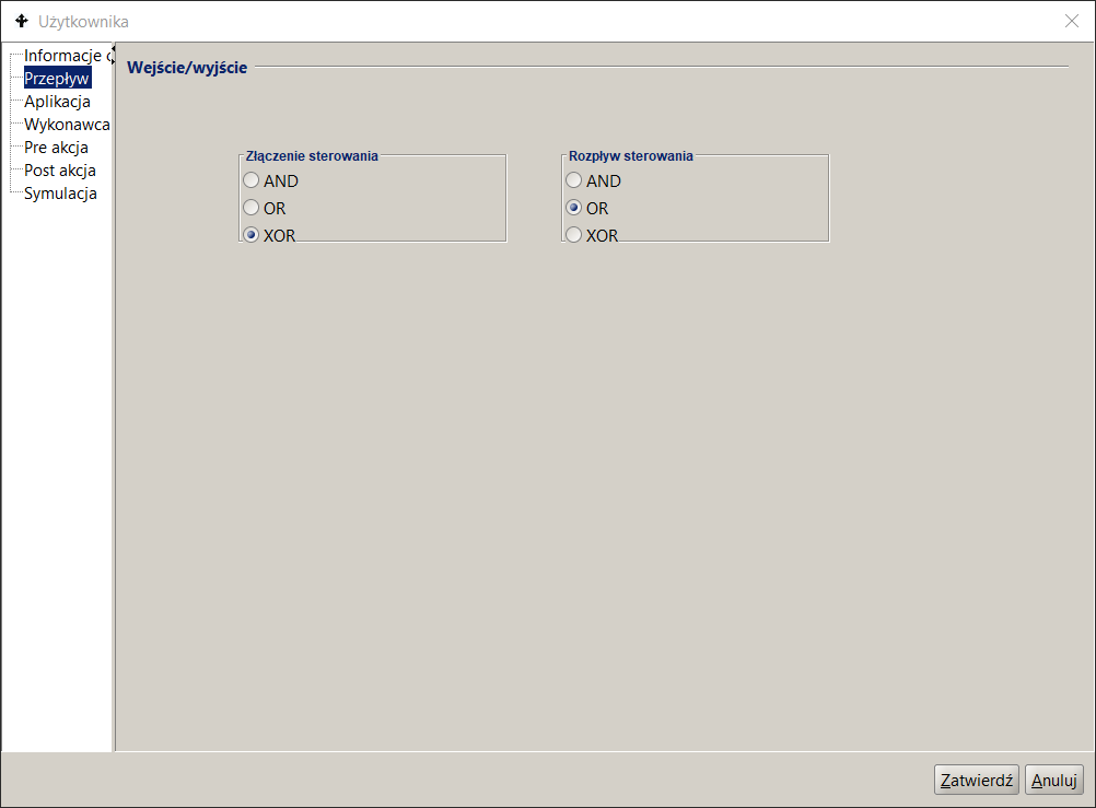
Figure 12. Incoming and outgoing flows defined in Activities
Performers
Another important element of defining an activity is to determine the performer ( s ) of the activity . To do this, you first need to clarify the meaning of roles in the process. In the next step, you need to use the mechanisms for selecting and assigning performers and define them for all activities occurring in the process.
- The docuRob®WorkFlow system provides three mechanisms for selecting and assigning performers: a BPQL rule to designate candidates as performers, a definition of how performers are selected from the list of designated candidates, and a method for assigning tasks to performers .
- Assignment of performers is performed in two stages. During the initial assignment, the BPQL rule designating performers is evaluated . As a result of its execution, a set of potential performers of the activity is obtained . This set can be either single-element or multi-element (many performers). Depending on the type of decision made, this set automatically becomes a list of performers of the activity (decision " Auto ") or is subject to verification by selected employees (decision Select).
- Tasks (activity instances ) are created for such selected participants . These tasks appear in their respective task lists. Depending on the set cardinality , after a task is picked up by any of the participants, the tasks of other participants are deleted (cardinality One) or remain to be performed (cardinality All). The details of the described elements are explained in the following sections.
Assigning Participants
The assignment of participants is expressed using a BPQL rule . The rule must return a set of participants (i.e. type SET<Participant> ) as a result. This set can also be single or multi-element.
The activity can be performed by People or automatic (performed by the System ). In the case of an automatic activity, the following should be specified as the person performing the activity:
['system']
To define a performer selection rule , you should ( Figure 13 ):
- in the process list panel , click on the process in question,
- go to the Process Model tab in the right panel . Find the appropriate activity and double-click. The activity properties dialog will appear on the screen,
- click on the " Performer " node. Enter the appropriate BPQL rule into the field .
When defining a performer selection rule, you can use built-in BPQL functions , selected elements of the organizational structure , and defined global variables . Access to these elements is possible after pressing the " Insert " button . Elements of the defined expression are highlighted using the appropriate color scheme. Texts, language instructions, or BPQL functions are marked differently.
After pressing the " Confirm " button, the entered expression is verified (unless the Verify BPQL expressions option is unchecked in the process design tool configuration ). If any errors are identified, appropriate information appears on the screen.
The decision enables the final verification of the list of candidates for performers by authorized persons. An example is the appointment of an appropriate employee who will deal with the case only after analyzing what the case concerns. In such a case, the system provides the decision-maker with a list of candidates to perform this activity and the decision-maker , having such a narrowed list, selects the appropriate employee.
in the docuRob ® WorkFlow system :
- Auto – the system automatically assumes that all designated candidates become the potential performers of this activity,
- Select - there is an option to select from a list of employee candidates who will become performers . From one to N candidates can be selected from the set of candidates, where N is the number of all candidates.
Selecting the appropriate decision type is performed in the Performer selection dialog box, in the " Decision " group.
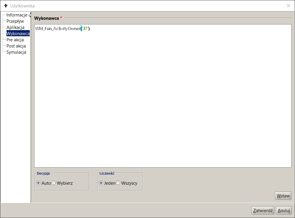
Figure 13. Entering the rules for assigning Performers
Cardinality
Sometimes there is a need for a given task to be performed by any employee of a group. One way to deal with such a situation is to assign this task to all employees of that group and after the task is started by one of them, to delete this task from the remaining employees.
The above needs are implemented in the docuRob® WorkFlow system using the Cardinality modifier . Cardinality determines how many performers will actually perform the activity. Currently, there are two options available:
- One – the activity will be assigned to all performers as separate tasks . Once the task is accepted by any of the performers, the tasks of the remaining performers will disappear (be removed) from their task lists.
- All - the activity will be assigned to all performers as separate tasks . After the task is received by any of the performers, the tasks of the remaining performers will remain on their task lists
Application
Actions performed automatically or with the participation of the user of the process are supported by calling an Application. This call is specified as part of the definition of the activity and it includes the specification of the application as well as the input parameters and the results returned by it.
To define an application in an activity:
- in the process list panel, click on the given process ,
- go to the Process Model tab in the right panel . Find the appropriate activity and double-click. The activity properties dialog will appear on the screen,
- click on the Application node. The Application definition screen is shown in Figure 14
- In the Protocol field, select the method of communication with the application from the list. The protocols are described in the following section,
- provide the name of the application and the method of its implementation, called a service. Depending on the communication protocol, the service identifies the application (indicates a Java class that represents the application ) or specifies what operation (method) will be performed within the application,
- specify input and output parameters .
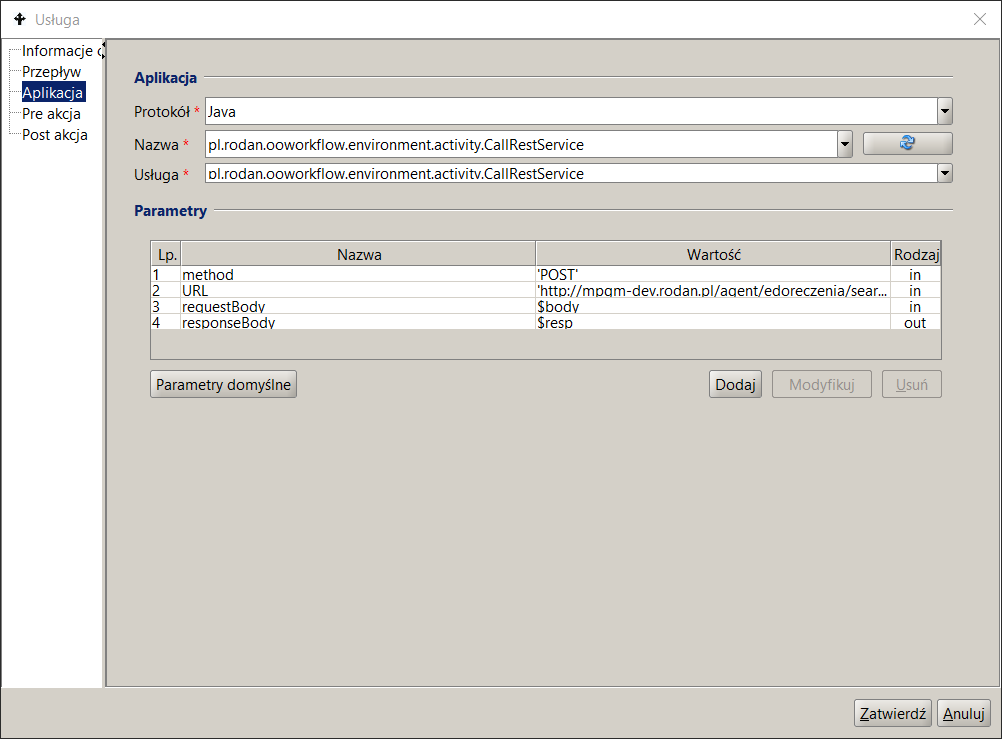
Figure 14. REST Service Connector Call Specification
Creating tasks that use the REST protocol and SOAP web services is presented in the Activities and Process Flows chapter.
Call protocol
docuRob®WorkFlow system supports three call protocols:
- Java – The application implements the external application interface defined in the docuRob® WorkFlow system and is implemented as a Java class. This protocol works only in synchronous mode. The service field specifies the full location of the class (packages and class name).
- URL – the application is invoked using the URL ( Uniform Resource Locator ) available via the HTTP protocol. This protocol is primarily characterized by invoking the action of the User type. This protocol works only in synchronous mode. The Service field specifies the specific address of the invocation.
- WebService – a service specification is provided, a list of input and output parameters is automatically loaded. This protocol characterizes the invocation of an automatic action and works in asynchronous mode. The Name field specifies the name of the service and the Service field specifies the name of the invoked operation in this service.
Network service
Figure 15 shows an example of a web service call based on the SOAP protocol.
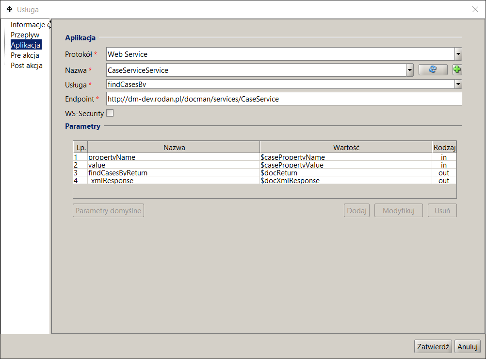
Figure 15. SOAP Web Service Call Specification
Assigning input parameters and results
Defining the input and result parameters is done by clicking the Add button. A window appears on the screen where you need to enter (see Figure 14 ):
- parameter type - the parameter can be input or output.
- parameter name - if the application specification was read automatically, the parameter name is already entered.
- parameter value For an input parameter, this can be any expression in BPQL with a type compatible with the parameter type. For an output parameter, this must be the name of a global variable or a process output parameter to which the returned value will be assigned.
Subprocess
In a complex activity, another process treated as a Subprocess is invoked . This invocation is performed in synchronous mode. The invoked Process is treated as an application and when defining a complex activity, mappings to the input and output parameters of the Subprocess must be specified .
To define a Subprocess in a complex activity , you must:
- in the process list panel, click on the process in question,
- go to the Model tab in the right panel process . Find the appropriate activity and double-click. The activity properties dialog box will appear on the screen,
- click on the Process node .
- In the Name field select the appropriate process (see Figure 16 ). Once a process is selected, the docuRob®WorkFlow system will automatically rewrite the list of input and output parameters of the selected sub-process .
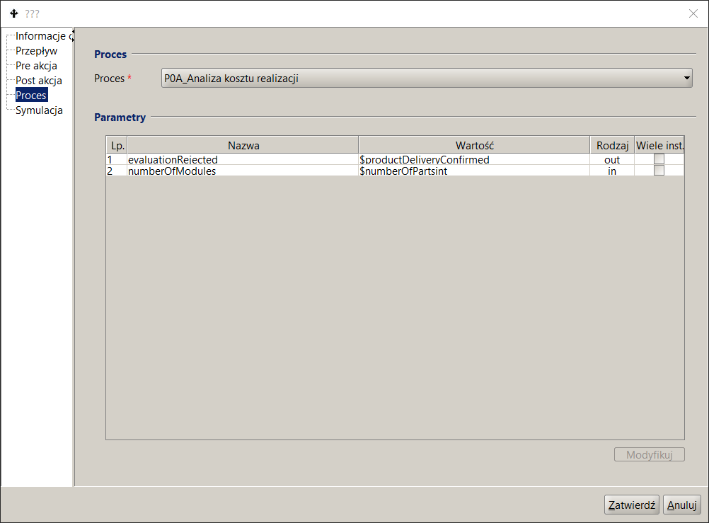
Figure 16. Subprocess call specification
Time constraints
docuRob®WorkFlow system supports defining time constraints at the process level and at individual activity levels. At the process level, it is possible to define the maximum process execution time . This time is expressed in days and hours . For a given instance, this time is counted from the moment the process is started. Exceeding the defined time causes the entire process (process instance) to be delayed. Additionally, it is also possible to define a rule for selecting an employees who should be notified in the event of a delay. This rule has the same limitations as the rules for selecting performers in activities.
To define a constraint at the process level :
- In the process list panel, click on the desired process.
- In the right panel, click on the lower Process Execution Information tab.
- Enter the appropriate values in the day and time fields.
- Implement a BPQL rule designating which employees will be notified in the event of a delay.
Constraints can be defined in two ways:
- In the form of days and hours.
- As a percentage of the maximum process execution time.
If during process execution these constraints are not met, then:
- The activity will be delayed.
- Depending on whether or not this activity is on the critical path, the entire process will be delayed .
If an activity is executed multiple times in a loop, the time count starts at the first execution of this activity and ends at the last execution.
Determining the owner of a process instance
The owner of the executed process (process instance) should be defined already at the stage of process identification. On the other hand, its proper definition can often be given only after the preparation of the full process definition. The definition of the process owner is represented by a BPQL rule , just like in the case of the rules for selecting the participant, i.e. the Work Participant Assignment (WPA) rule. .
To avoid problems with incorrect process owner assignment, the owner selection expression should be as simple as possible. It is best to specify the process owner, if possible, With surname and name - the same for all instances.
To define a process owner , you must:
- In the process list panel, click on the desired process .
- In the right panel, expand the Owner field instance " .
- Define a BPQL rule to determine the process owner.